Design Features
Development software; part of the Automation 3200 platform
Deploy complex machine and motion control
Connect to and deploy programs to the A3200 software-based machine and motion controller
Provide powerful tools for setting up and configuring A3200 drive solutions
Manage sensors and devices via EtherCAT, PROFINET, and Modbus configuration tools
Simulate your process before going live
Deploy powerful real-time application solutions
A development environment for every member of your team
One Software. Many Solutions.
The A3200 Motion Composer Suite is the development solution your team needs. Part of the Automation 3200 machine and multi-axis motion control platform, the Motion Composer suite allows your team to deploy complex automation solutions. The suite includes the following applications:
Mechanics and Controls Under One Roof
Aerotech knows what software features are needed to drive performance. We have learned it from our engineering and manufacturing team living under one roof since 1970.
Not only do we design and build precision stages and controls in the same building, but we test and validate customer applications using a “system” approach. The A3200 software tools are designed to enable meeting those system specifications. As a company locked into the precision mechanics market, our software, controls, and drives continuously evolve to meet those demands.
Connect and Go
The A3200 Platform makes setting up your motion control solution easy. Quickly set up drives, motors, and stages with the Configuration Manager application. This is one of the several tools integrated in the Motion Composer Suite that makes your team fast and effective. Team members work together to quickly develop a new solution or they can work from an existing configuration with advanced parameter importing and exporting tools.
Setting up process automation is also quick and easy. The A3200 Motion Composer Suite has integrated tools for configuring an EtherCAT, PROFINET, or Modbus Fieldbus network. Fieldbus I/O and expandable I/O on Aerotech drive hardware is directly accessible within the AeroBasic real-time programming language.
Develop and Test Real-Time Applications
The A3200 Motion Composer Suite includes a powerful environment for real-time developers. With the Motion Composer IDE you can develop, debug, and deploy real-time application code to the controller. The Motion Composer IDE can connect to a “virtual controller” and simulate your application in a virtual mode. This is a powerful development feature that allows engineers to prove-out complex processes.
For developers who aren’t working at the real-time level and prefer a standard programming language, the controller can be accessed via .NET, C, and C++ libraries; a REST API; a MATLAB library; and LabVIEW VIs.
Tune and Optimize Your Process
Optimize motor setup and servo performance with the Digital Scope’s optimization tools. Ensure your motor is phased and commutating correctly and that the encoder is optimized for performance. Continue to optimize by evaluating the servo loop and using powerful loop shaping tools to maximize performance.
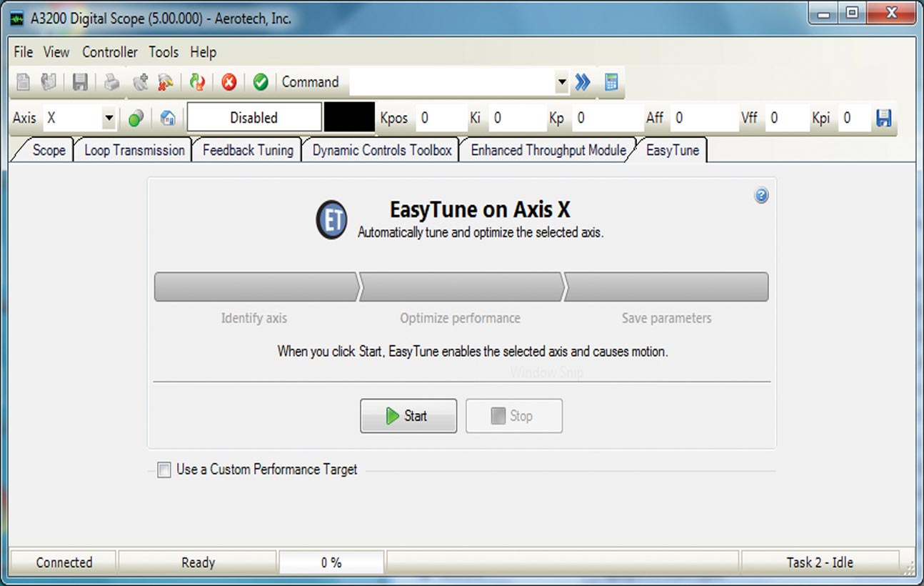
Or take the easy route. Use Aerotech’s EasyTune one-button servo optimizer that makes tuning simple.
Getting Results
The Motion Composer Suite can optimize applications that use different types of motion including point-to-point, contoured, and holding position. It can optimize your application no matter the level of precision. Run your motion program on the controller while the Digital Scope collects position, velocity, and acceleration commands, feedback, and error. The results are plotted in multi-dimensional views, and Fourier transforms are performed to identify any troublesome frequency content.
Relationship-Driven Support
During each phase of your development process and your machine’s operational life cycle, we have a team ready to support your needs. Our Field Sales and Application team is an extension of your design team even while you are still considering solution options for your system.
When engineering your solution, Aerotech continues to serve as a resource to your team. We can be brought on as a design partner, or we can offer a simple consultation. Customers use our system engineering expertise to expand upon their own capabilities.
As you build, commission, operate, and service your system, Aerotech’s Global Technical Support team supports and guides your efforts. We have technology experts that can optimize your process and develop code for your machine.

Set Up Your Devices
Use the Configuration Manager to set up and manage all of the devices in your automation solution. Parameters that are stored on the controller and drive electronics are set up and managed with the Configuration Manager. In additional to parameters, the configuration manager also manages program automation files and fieldbus configurations.
Help is easy to access. Simply click on the item you are setting up and the help screen updates with detailed, relevant content.

Single-Button Drive Configuration
One of the benefits of Aerotech’s HyperWire motion bus is the simplicity of configuring drives to communicate on the bus. Use the HyperWire glass-optical-fiber cables to connect the drives, and then power on the drives. Hit the “program” button in the Drive Configuration tool to automatically assign the communication channels. You are now ready to program the devices!

Don’t Guess. Calculate!
Aerotech makes setting up an automation solution simple. Quickly program your system’s motors and stages with the Axis Parameter Calculator. All of Aerotech’s mechanical stage and motor drive products are included in a detailed database, accessible through the Axis Parameter Calculator. Choose your mechanics and verify the load, motor, drive, programming units, feedback type, servo-loop target performance, and (optional) current loop target performance. Click “apply” and you’re done. Your system is now ready for detailed tuning and optimization.

Single Button Simplicity
Simplify the process of tuning and optimizing your motor through a series of single push-button tools. Some of the tools’ functionalities include:
Setting up proper motor phasing
Correcting Lissajous errors from analog encoders
Tuning the motor
Running a loop transmission
Best-fitting filters based on a loop transmission
Know What You’re Working With
Aerotech’s Motor Phasing Calculator is used to verify incorrectly wired motors. With the push of a button, this calculator identifies and compensates for unexpected motor power wiring and misalignment between the motor phasing and the feedback device. These corrections are accessible through the push of a button, and are required checks for AC brushless motor with and without Hall effect switches.

Feedback You Can Trust
Performance of an analog sine-wave encoder is optimized when the Lissajous pattern is corrected. A process that once required an oscilloscope is now performed with a single click of a mouse. The Feedback Tuning tool applies a simple move to the stage and graphically displays a Lissajous pattern with the correct phase and amplitude adjustments.

EasyTune
EasyTune® is the most advanced autotuning tool available. Entirely data-driven, the algorithm mimics the process followed by an experienced controls engineer. EasyTune begins with a system identification operation. It continues with the development of a baseline stabilizing controller followed by progressively more sophisticated compensation via loop-shaping procedures. In just minutes, the system has the highest bandwidth practical, all with no input from the user!
Advanced Tuning for Advanced Users
For users who prefer or require becoming more familiar with servomotor tuning, advanced tuning tools are available.
Aerotech supports 11 different response types, five different digital filter types, plus the ability to autofit digital filters, three different excitation methods, pole-zero plots, quick loop shaping tools, and many more advanced features.
These advanced tools make it simple to evaluate and optimize complicated systems.
Also, Aerotech can work with you to optimize your system. Not only do we have powerful tools, but we also have motion control experts that are partners in your success.

Powerful Programming
The A3200 Motion Composer IDE is a powerful part of the software suite for developing an automation control scheme. With the Motion Composer IDE you can write and debug programs using standard program execution controls (start, stop, pause, compile, etc.), and standard debugging controls (breakpoints, step into, step over, and syntax highlighting).

More than Motion
The ability to combine motion control with process tools and automation makes the AeroBasic™ programming language the motion control industry’s most powerful tool. Access language features such as program flow control, a set of galvo commands that integrate laser control with galvo scan-head motion, a TCP/IP communication library, math functions, I/O commands, file and serial port communication commands, and several advanced controller features. When the CNC option is purchased, in addition to all the functionality listed above, customers can use AeroBasic motion commands, G-Code commands, and much more in a single, non-delineated programming language.
Additional features include a detailed error explanation, full diagnostic debugging tools, a watch window that shows variable values for easy debugging, a link to the help file for a description of the error, and a full-featured CNC-style axis manager.


Debugging & Optimizing
Debug Your Automation Programs
The Motion Composer IDE includes powerful tools to help you review and debug your programs. You can insert breakpoints, run and pause your program, step into or step over subroutines, and toggle breakpoints.
All of these debug features are easily accessible on a top-level menu bar in the IDE.

Optimize Your Motion
Building a motion control centered automation solution requires that your motion is optimized. In the motion control world, throughput and accuracy are two important considerations.
The Digital Scope application has tools to detect how well the system is moving. Collect and analyze more than 70 standard axes signals and more than 50 standard task signals with a software oscilloscope capable of 2D graphs and FFT analysis.
Seeing this feedback allows you to determine how well your motion system is following the desired path, how fast it is settling into position, or how well it is holding a target position. When things aren’t working the way intended, you can monitor signals such as velocity feedback and current command feedback to get an idea of what could be causing the error.
Use the Scope tab in the Digital Scope in combination with Aerotech’s different tuning tools to optimize motor performance for the same level of motion performance.


Tools, Tools, and More Tools
Built for Expansion
Want to add a device to your database? No problem. The Catalog Manager lets you add an unlimited number of devices to your library. Use the Axis Parameter Calculator to quickly set up the motors and stages that you added to your device database.

Connected Automation
Aerotech offers Modbus, EtherCAT, and ProfiNET capability on its A3200 controller. You can easily set up those networks in the Configuration Manager. Simply launch the appropriate configuration tool, map your device, and start creating AeroBasic definitions. AeroBasic definitions become accessible as you begin programming your real-time control applications in the A3200 Motion Composer IDE.

Robust Control Tools
The A3200 Motion Composer Suite contains many robust controls tools. Tools like filter calculators for analog and digital inputs allow nuisance electrical noise to be rejected and for your systems to recognize input signals that require a response, not those that should be ignored. Throughout all of Aerotech’s software tools, you’ll find solutions built off of decades of automation experience.

Diagnose and Optimize
The Status Utility is a machine optimization tool that displays the status of up to 32 axes, all controller tasks, and several critical controller status details.
See axis information such as homing, enabled controller features, axis I/O, hardware limits, Hall effect sensors, and encoder feedback signals.
The Status Utility shows detailed information about each connected Aerotech drive and programming task. The status of axis and task faults and controller information, including performance and internal counters, are also shown on the Status Utility.
You can customize the information shown in the Status Utility by choosing what axes and tasks to display. You can also export data from the Status Utility to an HTML file.
Programming Libraries
.NET, C, and C++ Libraries plus REST Interface
Aerotech’s standard controllers are flexible enough to handle almost any control application. From simple motion to coordinating and synchronizing the motion of multiple axes in your machine, Aerotech automation controllers provide the flexibility and power required for today’s automation challenges, and it is all accessible through powerful programming libraries.
MATLAB® Library and LabVIEW® VIs
Users who program in MATLAB and LabVIEW can benefit from Aerotech’s powerful automation tools. Integrate into your native environment with well-documented libraries.
Specifications
A3200 Motion Composer Suite Software License Specifications
| Option | Configuration | Description |
|---|
| A3200 | Order Entry Point | Full installation of Automation 3200 controller and selected software components on a new system Pricing is summation of selected products. Maintenance (software update) included in price for one year from date of purchase. A3200 is intended for deployment on desktop or industrial PCs. See website for PC specifications. Includes: |
| License | Machine | Contains both the A3200 Motion Composer Suite and the A3200 Software-Based Machine Controller Provides the ability to: Write, compile, execute, debug programs in AeroBasic or G-code Full access to .NET, C, and C++ libraries Full access to REST web interface Access full diagnostics, fault, and status information Access and set I/O, registers, and variables Collect, analyze, and save data View files from machine for analysis and record keeping Connect PC to machine directly with FireWire or HyperWire card Connect PC to machine remotely through Ethernet TCP/IP Install upgrades (firmware or controller) using loader Two axes of software motion engine control Simulate trajectory on PC Installs INtime on the PC
|
| Machine Upgrade | Use to change configuration options on an existing machine license
Requires the current license ID from customer
Price is based on the new options added
Maintenance extension is a separate line item |
| Machine Addition | Increases the number of licenses associated with an existing key |
| License Extension | Extends the maintenance period on an existing license
Can be purchased in yearly increments |
| Media Only | License ID distributed on the specified media |
A3200 Configuration Manager Features
Use the Configuration Manager to change parameter files, set the active parameter files, establish the correct connection settings, and load program automation files tothe controller.
The main menu and toolbars give you access to almost all of the features that are available in the application. Below the main menu, the Configuration Manager has four window panes or sections:Network Explorer: Set up the controller and organize files.
Viewer: Shows contextual information about the current selection in the Network Explorer. For example, when you select a parameter category, all of the parameters in that category show in the viewer.
Editor: Modify the values of different items such as the name of a controller or the value of a parameter.
Help Browser: Shows the help topic for the subject that you select in the viewer.
Configuration Manager includes the following tools/wizards:
| Item | Tools/Wizards |
|---|
| Catalog Manager | Create a catalog of motors and stages that are not standard Aerotech motors and stages |
| Connection Settings | Configure the Drive Communication card, configure the Fieldbus settings you want to use with the A3200, configure the Connection Mode of the A3200 (local or remote), and configure the advanced options of the A3200 |
| Drive Configuration | Assign communication channels and load firmware for the HyperWire drives that are connected to your controller |
| Compiler Output Directory | Set the output directory that the AeroBasic compiler uses when it compiles an AeroBasic program |
| Axis Naming Tool | Simple tool to assign customized axis names to controller axes 1 through 32. An axis name can be any string of letters, numeric digits, and underscores. |
| Program Automation | Automatically run programs or include them within other programs. These programs are automatically run, included, or downloaded when you start or reset the A3200. |
| Fieldbus Mapping Tool | Create and edit the Fieldbus mappings that are stored in your parameter file |
| AbsoluteFeedbackOffset Calculator | Calculate the correct value for the AbsoluteFeedbackOffset Parameter on piezo stages |
| Analog and Digital Filter Calculators | Calculate coefficients for the two filters on analog and digital inputs that are available on each axis |
| Axis Parameter Calculator | The primary calculator to use to configure an axis. You can use this calculator to configure axis types that include ball-screw stage, linear stage, rotary stage, voice-coil stage, and no stage (motor only). For each axis, you can specify information about the mechanics, drive, units, feedback, servo loop, and current loop. |
| Encoder Resolution Changed Calculator | Helps users to manage changes in encoder devices and encoder resolutions. This calculator comes into view when you change certain encoder and feedback parameters. |
| Gantry Home Offset Calculator | Calculates the correct value for the HomeOffset Parameter on the gantry slave |
| Motor Phasing Calculator | Calculates the correct values for parameters which allow you to compensate for motor wiring problems |
| Scaling Factors Changed Calculator | Scales other parameters that are entered in user units to match a new CountsPerUnit value |
A3200 Motion Composer IDE Features
A3200 Motion Composer IDE is an environment for developing and debugging AeroBasic programs for A3200 controllers. It has a feature-rich program editor with the following features:
Line number indicators (for each line)
Breakpoints (indicated by a breakpoint icon)
Current Line indicator (indicates the next line to be executed)
Status bar (indicates the file path, line, column, and character number)
Syntax highlighting:
It also functions as a basic interface and can be used to do the following tasks.
Command basic motion
Inspect diagnostic information
Do basic configuration (for advanced configuration options, use Configuration Manager)
Editing Programs
Each controller task is identified by a tab. You can open program files in a specific task tab and debug programs that are running in that task. If you open files in multiple task tabs, the files are linked together. If you make changes to one file, the changes are applied to all linked files.
Building and Loading Programs
When building programs, the build file is always the active file and is always an .ab or .abl program. The Compiler output is sent to the Output Window, and errors are shown in the Error List. Loading a program builds the current AeroBasic program, loads it onto the controller, and sets the task to the Program Ready state. You can then execute the program.
Simulation Mode
The Automation 3200 Platform allows you to test or debug programs without moving some or any of the axes, allowing you to develop or debug your motion program before hardware and motion mechanics are ready. Simulation mode occurs when you use Virtual or Null Axes.
Virtual Axis: there is not a configured drive for that communication channel, so you don’t create motion or torque on an axis.
Null Axis: the servo loop is bypassed, and the position and velocity feedback are set equal to the position and velocity commands, respectively. Position error and velocity error are always zero.
Running and Debugging Programs
In the Motion Composer IDE, you can take advantage of a full suite of tools to run and debug programs in both Simulation and Live Mode.
To run in Simulation Mode, simply set up the axes as virtual or null, as described above. To run and debug a real process, first make sure that the system is set up correctly.
The following actions are available for running and debugging a program:Run the selected AeroBasic program
Pause the active program
Stop the program associated with the active task
Stop all programs (on all tasks)
Toggle a breakpoint
Clear all breakpoints
Toggle line highlighting
Variable Watch
View and edit the value of Global Variables, Task Variables, Program Variables, Virtual Binary I/O Bits, and Virtual I/O Registers
Step Over
Executes one line of the program that is associated with the active task
For a subroutine call (CALL or FARCALL), it executes all of the subroutine and moves to the next program line
Step Into
Executes one line of the program that is associated with the active task
If the program line is a subroutine call (CALL or FARCALL), it steps one level into the subroutine
Issue Immediate Commands
An immediate command is a one-line AeroBasic program that executes on a task. These commands are issued from the Command Box or by using the IMMEDIATE EXECUTE AeroBasic command from a program. This functionality is perfect for simple commands such as:Asynchronous motion commands
Setting parameters via AeroBasic commands
Setting variables
Setting modes (for example, absolute/incremental programming modes)
Most immediate commands can execute on a task at the same time a program is running on that task. Some of the more complicated commands require that the task program is stopped.
A3200 Digital Scope Features
The A3200 Digital Scope is a system analysis and tuning application that lets you optimize system performance using a collection of advanced tuning tools and features. With system analysis tools, you can plot and graphically analyze system data. With tuning tools, you can automatically calculate servo-loop and feedback device parameters.
The Digital Scope application includes a variety of utilities that let you perform analysis and tuning operations.
Scope: A Powerful Digital Oscilloscope
The Scope tool is used to collect and view 1D or 2D data. A Configure Data Collection tool gives you access to all Axis, System, and Task data items. Customize the signals that you are interested in seeing, the resolution of collection, the number of points, and how the signals will appear on your visual plotter. Enjoy zoom in, zoom out, zoom extents, and dual cursor controls as you evaluate your data in 1D or 2D format. Quickly switch between 1D and 2D and perform Fourier Transforms on collected signals.
Integrate data collection when you using Step Forward, Step Back, and Auto Step controls. These tools allow you to configure simple axis motion and coordinates data collection, as configured with that motion.
The Scope Tool also provides the capability to autotune the servo loop of an axis. Use autotune to calculate a set of servo loop gains. Simply excite the axis using a predefined input. The output is measured and new servo loop gains are calculated by the autotune feature.
EasyTune: More Automatic than Autotuning
EasyTune is a one-button tool that automatically tunes and optimizes an axis. When EasyTune is finished, the optimized servo gains and servo filters are committed to the controller.
Loop Transmission: For Those Who Analyze
Use the Loop Transmission utility to analyze the characteristics of the servo loop and the associated mechanical system. The Loop Transmission measures the response of the servo loop. Signals are sampled and displayed for magnitude and phase analysis.
Powerful “loop shaping” tools are available to the user. These tools work with the existing data and show a prediction of an updated loop transmission response plot should new servo gains and parameters be applied. These loop shaping tools include:
Warnings for feedback data that indicate unstable behavior
Single button optimization of the servo loop gains and digital filters
Single button assignment of all digital filters
Graphical shifts of the predicted open-loop magnitude and phase
Graphical additions of Low Pass, Notch, Lead Lag, and Resonant filters
Direct editing of the digital filters in the frequency response plotter utility
The ability to overlap multiple loop transmission plots
Feedback Tuning: Removing Error from Precision Feedback Devices
Tune the feedback device signals so that optimum performance can be achieved. This utility can only be used with analog feedback devices. The goal of the feedback tuning utility is to tune the feedback device so that the Lissajous pattern received from the feedback device closely matches the ideal Lissajous circle pattern. This tuning is applicable to sine-wave encoders and resolvers. It can also be applied to situations that use dual loop sine-wave (position and velocity) tuning.
Add-On: Dynamic Controls Toolbox
The Dynamic Controls Toolbox includes a collection of controller-level algorithms designed to improve machine positioning, increase throughput, and reduce cycle times. These tools include: Harmonic Cancellation, Command Shaping, and Cross-Axis Feedforward.
Add-On: Enhanced Throughput Module
The Enhanced Throughput Module (ETM) is a physical sensor that is added to your mechanical motion system. It can improve machine throughput by measuring base or frame vibration directly and using this information in the servo control algorithm. The Enhanced Throughput Module interface in the Digital Scope allows this sensor and its input to be configured on the controller.
A3200 Status Utility Features
The Status Utility is a machine optimization tool that displays the status of up to 32 axes, all controller tasks, and several critical controller status details.
Axis Information
Axis status information, such as homing and enabled controller features
Axis I/O information, including hardware limits, Hall effect sensors, and encoder feedback signals
Diagnostic and status information for each connected Aerotech drive
Detailed information and status concerning each connected Aerotech drive
Current axis fault status
Additional Information
Status information about each task
Controller information, including performance and internal counters
Data collection status
Customizable Interface
Export Customized Data
Choose which data you want to export: axes, tasks, and/or other
Export data directly to an HTML file
A3200 Console Features
The A3200 Console is a command line interface used for low-level system hardware debugging. It reads commands from text files (similar to batch files) so that you can execute multiple commands as if they were one command. It also provides a status and integrated Help.

A3200 Firmware Features
The Firmware Loader shows all of the drives connected to the system upon opening or refreshing and determines if a new version of firmware should be loaded on the drive to maintain compatibility with Motion Composer and the Machine License loaded on the PC.
Ordering Information
A3200 Motion Composer Suite
| Product Name | Description |
|---|
| A3200 | A3200 Motion Composer Suite |
License Options
| Option | Description |
|---|
| License |
| -Machine | A3200 software installation on a single PC |
| -Machine upgrade | A3200 software configuration change of license |
| -Machine addition | A3200 software increase license count for existing key |
| -License extension | A3200 software extend maintenance period of license |
| -Media only | A3200 software distribute current license on media |
| Media |
| -Download | Installation media provided for download only |
| -USB | Installation media provided on a USB drive |
| -CD | Installation media provided on compact disk |
| Version |
| -Default | Current version of software/controller |
| -Legacy | Legacy version of software/controller |
| Maintenance |
| -Maintenance-X-00 | Software/controller maintenance for x year(s) after purchase where X is one through seven. One year is default. |
Software-Based Controller Configuration
| Option | Description |
|---|
| Axes |
| -2 Axes | Provides the ability to connect to 2 physical axes (default) |
| -4 Axes | Provides the ability to connect to 4 physical axes |
| -6 Axes | Provides the ability to connect to 6 physical axes |
| -8 Axes | Provides the ability to connect to 8 physical axes |
| -10 Axes | Provides the ability to connect to 10 physical axes |
| -12 Axes | Provides the ability to connect to 12 physical axes |
| -14 Axes | Provides the ability to connect to 14 physical axes |
| -16 Axes | Provides the ability to connect to 16 physical axes |
| -32 Axes | Provides the ability to connect to 32 physical axes |
| Fiber Optic |
| -Fiber Optic | Fiber optic power scanning and virtual pivot point utilities |
| Dynamic Controls Toolbox |
| -Dynamic Controls Toolbox | Aerotech Advanced Controls |
| Enhanced Throughput Module |
| -Enhanced Throughput Module | Setup and monitoring screens for ETM modules |
| CNC |
| -CNC | G and M codes plus other machine tool functionality |
| Professional |
| -Professional | 31 user tasks, 1 library task, 31 Modbus connections |
| EtherCAT |
| -EtherCAT | EtherCAT software driver for Hilscher-RJ45 PCI card |
| PROFINET |
| -PROFINET | PROFINET software driver for Hilscher-RJ45 PCI card |
| Enhanced Tracking Control |
| -Enhanced Tracking Control | Reduced dynamic following error and settling times |
| Remote Server |
| -Remote | Configure A3200 as server |
Motion Composer Suite Add-Ons
| Option | Description |
|---|
| CNC Operator Interface |
| -CNC Operator Interfacer | HMI CNC software for Windows. Includes the CNC option |
| Motion Designer |
| -Motion Designer | Trajectory creation and evaluation software |
| Motion Simulator |
| -Motion Simulator | Trajectory simulation, creation, and evaluation software |
| LabVIEW |
| -LabVIEW | Includes LabVIEW 2010 (forward compatible) VI samples |
| MATLAB Libraries |
| -MATLAB | MATLAB library for motion, parameters and data collection |
FireWire Communication Network (Items Ordered Separately)
| Option | Description |
|---|
| NFire-PCIe |
| NFire-PCIe | Firewire communication network PCIe card (recommended) |
| NFire-PCI |
| NFire-PCI | FireWire communication network PCI card |
| NConnect-6P6P-xx* |
| NConnect-6P6P-45 | FireWire cable (4.50 meter length), 6P to 6P |
| NConnect-6P6P-30 | FireWire cable (3.00 meter length), 6P to 6P |
| NConnect-6P6P-18 | FireWire cable (1.80 meter length), 6P to 6P |
| NConnect-6P6P-9 | FireWire cable (0.90 meter length), 6P to 6P |
| NConnect-6P6P-5 | FireWire cable (0.50 meter length), 6P to 6P |
| NConnect-6P6P-2.3 | FireWire cable (0.23 meter length), 6P to 6P |
HyperWire Communication Network (Items Ordered Separately)
| Option | Description |
|---|
| HyperWire-PCIe |
| NFire-PCIe | Firewire communication network PCIe card (recommended) |
| HyperWire-AO10-xx |
| HyperWire-AO10-200 | HyperWire cable (20.0 meter length), SFP to SFP |
| HyperWire-AO10-50 | HyperWire cable (5.0 meter length), SFP to SFP |
| HyperWire-AO10-30 | HyperWire cable (3.0 meter length), SFP to SFP |
| HyperWire-AO10-10 | HyperWire cable (1.0 meter length), SFP to SFP |
| HyperWire-AO10-5 | HyperWire cable (0.5 meter length), SFP to SFP |