Design Features
Closed-loop, two-axis servo drive for Aerotech’s AGV series scanners
Infinite Field of View (IFOV) seamlessly combines AGV and servo motion to expand the scanner work area
Full servo state control with “zero-tracking error” eliminates speed-related part distortion such as necking on circles and rounding of corners
HyperWire® fiber-optic interface
External clock input for synchronization with mode-locked lasers
Position-based laser firing (PSO) with windowing maintains consistent spot spacing over a wide range of operating speeds
Part-Speed Position Synchronized Output (PSO) included
High-Resolution Feedback
The AGV-HP has thermally stable feedback transducers with virtually no gain or offset drift. The GL4 uses advanced interpolation electronics to provide up to 26-bits of effective resolution. Onboard real-time 2D calibration ensures accurate beam placement over the entire field of view.Position Synchronized Output (PSO)
The ability to accurately place a laser spot as a function of X/Y axis position is a key feature of Aerotech’s linear positioning tables for laser processing applications (See Figures 1 and 2). With the release of the GL4, this functionality is now available for scanner applications. The ability to accurately trigger the laser as a function of position removes the need to program mark, jump, and polygon delays, resulting in reduced programming complexity. By using the Position Synchronized Output functionality, scanner-based processes can now be programmed in the same fashion as traditional X/Y stage-based applications.Remote Power Devices
Most competitive scanners have the power devices integrated directly into the head, along with the galvos and feedback devices. These power devices can inject considerable thermal energy into the scanner head causing drift in the feedback positions and changing offsets between the mirrors, all of which reduce marking accuracy. Some systems use PWM power stages to minimize heat input. However, this approach results in reduced tracking accuracy due to nonlinear effects that are present when the galvo motors and control currents reverse polarity. By moving the power stage out of the head, it is possible to use higher performing transistors to drive the galvos and the heat source is effectively removed from the scanner resulting in improved system accuracy (See Figures 3 and 4).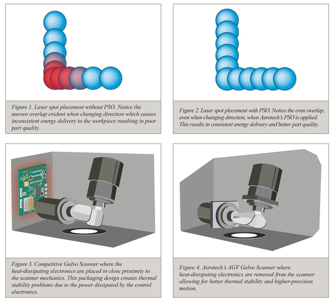
Additional Resources
Galvo Calibration File Converter (GCFC) – Use the GCFC to create new, optimize existing, or convert third-party calibration files for operation with the GL4.
You may be interested in Aerotech's recent webcast, Accuracy of Combined Scanning and Servo Systems.
Summary: Linear and rotary actuators are often used to expand the effective working area of scanner/galvo marking heads. This presentation will discuss alignment, scaling, rotation, and stitching-induced errors and their combined impact on final part quality. Advanced error correction, path planning, and laser triggering techniques that help to minimize these errors will also be presented.
To access the archived presentation, please click HERE.

