Specifications
AGR Specifications
| Mechanical Specifications | AGR50 | AGR75 | AGR100 | AGR150 | AGR200 | |
|---|---|---|---|---|---|---|
| Travel | 360° (Limited Travel Versions Available) | |||||
| Accuracy | Uncalibrated | 0.87 mrad (180 arc sec) | 0.58 mrad (120 arc sec) | |||
| Calibrated | 0.29 mrad (60 arc sec) | 0.24 mrad (50 arc sec) | ||||
| Uncalibrated with Direct Encoder Option | 97 µrad (20 arc sec) | |||||
| Calibrated with Direct Encoder Option | 58 µrad (12 arc sec) | 49 µrad (10 arc sec) | ||||
| Repeatability (Unidirectional) | Standard | 49 µrad (10 arc sec) | ||||
| Direct Encoder(1) | 24 µrad (5 arc sec) | |||||
| Repeatability (Bi-directional) | Standard | 0.22 mrad (45 arc sec) | ||||
| Direct Encoder(1) | 39 µrad (8 arc sec) | 29 µrad (6 arc sec) | ||||
| Tilt Error Motion | 49 µrad (10 arc sec) | |||||
| Axial Error Motion | 5 µm | |||||
| Radial Error Motion | 10 µm | |||||
| Gear Ratio | 51:1 | 67:1 | 85:1 | 117:1 | 126:1 | |
| Maximum Speed(2) | with Brushless Servomotor (BM and BMS Models) | 180°/s | 120°/s | |||
| with Stepper Motor | 60°/s | 40°/s | ||||
| Maximum Acceleration(3) | 720°/s2 | 480°/s2 | ||||
| Aperture | 50 mm | 75 mm | 100 mm | 150 mm | 200 mm | |
| Load Capacity | Axial | 40 kg | 100 kg | 200 kg | 300 kg | 425 kg |
| Radial | 20 kg | 50 kg | 100 kg | 125 kg | 200 kg | |
| Moment | See Moment Load Curves | |||||
| Maximum Torque Load to Stage Shaft | 2.5 N·m | 3.5 N·m | 12 N·m | 20 N·m | 80 N·m | |
| Rotor Inertia (Unloaded) | 0.00052 kg·m2 | 0.0013 kg·m2 | 0.0035 kg·m2 | 0.011 kg·m2 | 0.076 kg·m2 | |
Stage Mass | Standard | 1.9 kg | 2.4 kg | 4.5 kg | 6.1 kg | 18.6 kg |
| Direct Encoder | 2.5 kg | 3.1 kg | 5.6 kg | 7.6 kg | 21.7 kg | |
| Material | Aluminum | |||||
Direct encoder repeatability specifications are for systems using the -E1 or -E3 direct encoder options only.
Maximum speed is load dependent. Contact an Aerotech Application Engineer if imbalanced loads are present.
Unloaded acceleration.
On-axis loading is listed.
Specifications are for single-axis systems measured 25 mm above the tabletop. Performance of multi-axis systems is payload and workpoint dependent. Consult factory for multi-axis or non-standard applications.
Electrical Specifications
| Model | AGR50 | AGR75 | AGR100 | AGR150 | AGR200 | |
|---|---|---|---|---|---|---|
| Drive System | Precision Worm-Gear with Brushless Servomotor or Stepper Motor | |||||
| Feedback | Standard | Noncontact Rotary Encoder Contained Within Motor; See Motor Description Under "Ordering Options" Section for Details | ||||
| Direct Encoder | Noncontact Rotary Encoder Directly Mounted to AGR Stage Shaft | |||||
| 15744 Lines/Rev | 18000 Lines/Rev | 23600 Lines/Rev | 31488 Lines/Rev | 40000 Lines/Rev | ||
| Maximum Bus Voltage | with Brushless Servomotor (BM Models) | 80 VDC | 320 VDC | |||
| with Brushless Servomotor (BMS Models) | 320 VDC | |||||
| with Stepper Motor | 40 VDC | 80 VDC | ||||
| Limit Switches | 5 V, Normally Closed or Normally Open | |||||
| Home Switch | Near Limit (for Limited Travel Stage Version) | |||||
For stepper motors with Aerotech controllers, amplifier bus voltages are 2X values listed.
Recommended Controller
| Multi-Axis | A3200 | Ndrive MP10/Ndrive CP10/Npaq | ||||
| Ensemble | Ensemble MP10/Ensemble CP10/Epaq | |||||
| Single Axis | Soloist | Soloist MP10/Soloist CP10 | ||||
AGR Specifications Graph 

Dimensions
AGR50  Enlarge Image
AGR50 Accessories 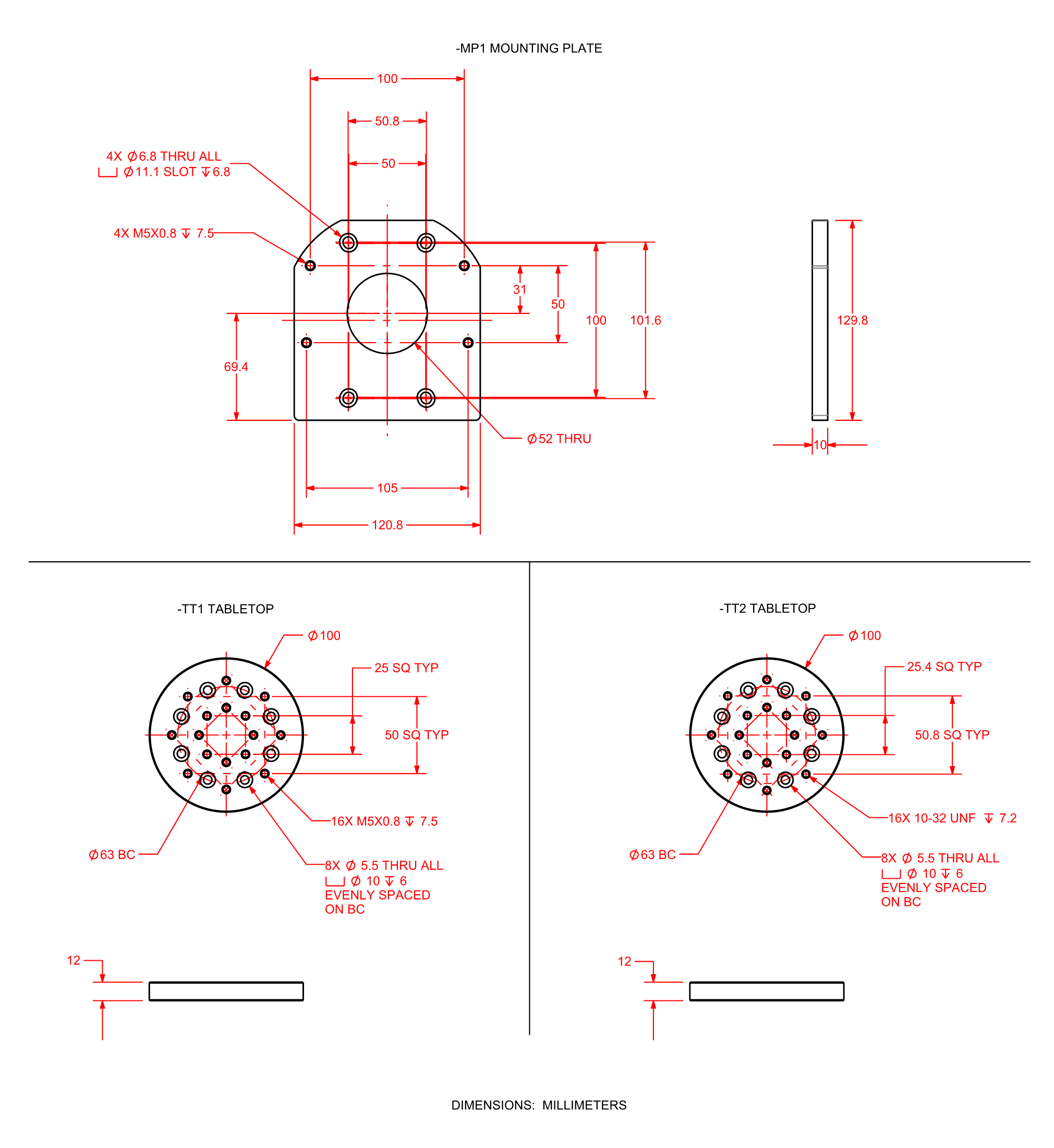 Enlarge Image
AGR75  Enlarge Image
AGR75 Accessories 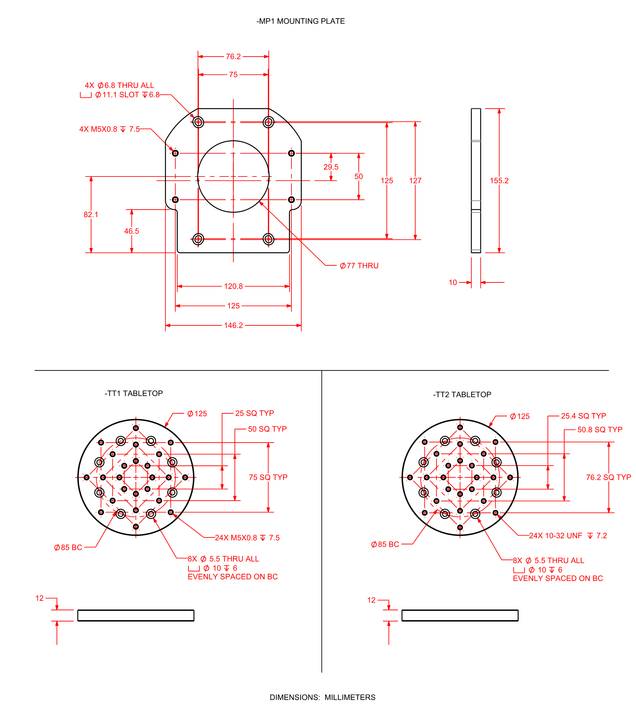 Enlarge Image
AGR100  Enlarge Image
AGR100 Accessories 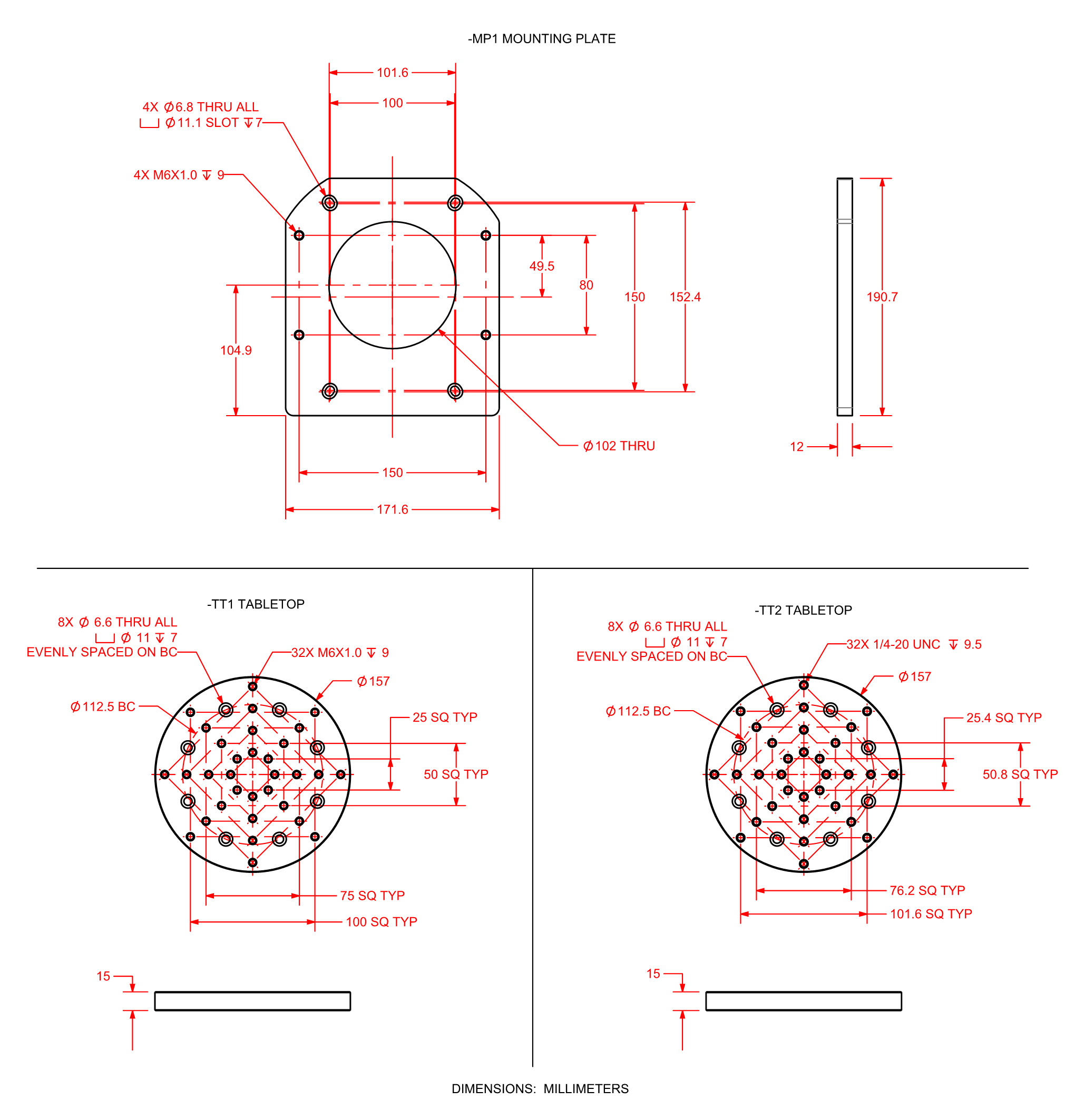 Enlarge Image
AGR150  Enlarge Image
AGR150 Accessories 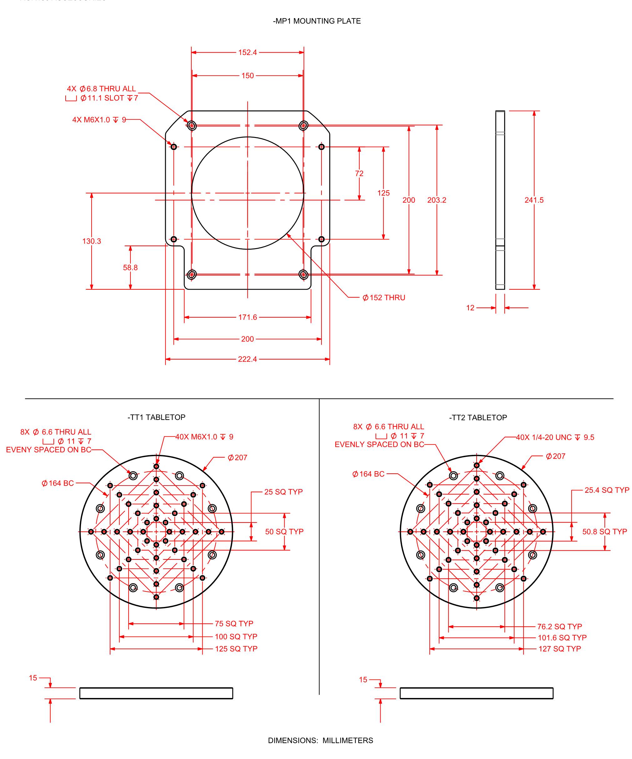 Enlarge Image
AGR200  Enlarge Image
AGR200 Accessories 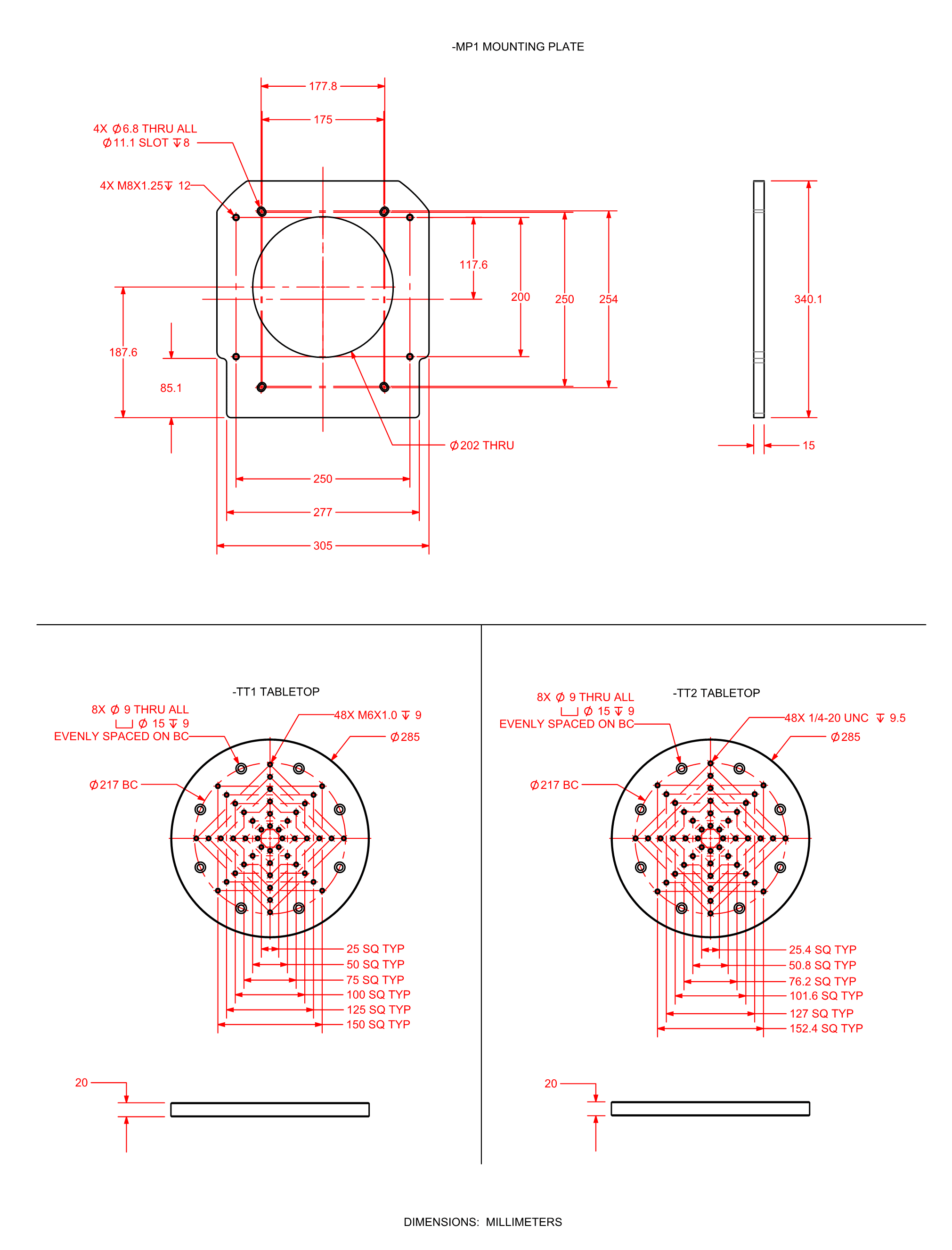 Enlarge Image
Ordering Information
AGR Series Gear-Driven Rotary Stages
Model (Required)
| Option | Description |
|---|---|
| AGR50 | Gear-driven rotary stage, 50 mm diameter clear aperture |
| AGR75 | Gear-driven rotary stage, 75 mm diameter clear aperture |
| AGR100 | Gear-driven rotary stage, 100 mm diameter clear aperture |
| AGR150 | Gear-driven rotary stage, 150 mm diameter clear aperture |
| AGR200 | Gear-driven rotary stage, 200 mm diameter clear aperture |
Motor (Optional)
| Option | Description |
|---|---|
| -M1 | BMS35 brushless servomotor and 2000-line TTL encoder (AGR50, AGR75) BMS60 brushless servomotor and 2500-line TTL encoder (AGR100, AGR150) BMS280 brushless servomotor and 2500-line TTL encoder (AGR200) |
| -M2 | BMS35 brushless servomotor and 2000-line TTL encoder with brake (AGR50, AGR75) BMS60 brushless servomotor and 2500-line TTL encoder with brake (AGR100, AGR150) BMS280 brushless servomotor and 2500-line TTL encoder with brake (AGR200) |
| -M3 | BMS35 brushless servomotor and 1000-line 1 Vpp encoder (AGR50, AGR75) BMS60 brushless servomotor and 1000-line 1 Vpp encoder (AGR100, AGR150) BMS280 brushless servomotor and 1000-line 1 Vpp encoder (AGR200) |
| -M4 | BMS35 brushless servomotor and 1000-line 1 Vpp encoder with brake (AGR50, AGR75) BMS60 brushless servomotor and 1000-line 1 Vpp encoder with brake (AGR100, AGR150) BMS280 brushless servomotor and 1000-line 1 Vpp encoder with brake (AGR200) |
| -M5 | BM22 brushless servomotor and 2000-line TTL encoder (AGR50, AGR75) BM75 brushless servomotor and 2500-line TTL encoder (AGR100, AGR150) BM250 brushless servomotor and 2500-line TTL encoder (AGR200) |
| -M6 | BM22 brushless servomotor and 2000-line TTL encoder with brake (AGR50, AGR75) BM75 brushless servomotor and 2500-line TTL encoder with brake (AGR100, AGR150) BM250 brushless servomotor and 2500-line TTL encoder with brake (AGR200) |
| -M7 | SM35 stepper motor (AGR50, AGR75) BM75 brushless servomotor and 1000-line 1 Vpp encoder (AGR100, AGR150) BM250 brushless servomotor and 1000-line 1 Vpp encoder (AGR200) |
| -M8 | SM35 stepper motor with brake (AGR50, AGR75) BM75 brushless servomotor and 1000-line 1 Vpp encoder with brake (AGR100, AGR150) BM250 brushless servomotor and 1000-line 1 Vpp encoder with brake (AGR200) |
| -M9 | SM60 high voltage stepper motor (AGR100, AGR150) SM280 high voltage stepper motor (AGR200) |
| -M10 | SM60 high voltage stepper motor with brake (AGR100, AGR150) SM280 high voltage stepper motor with brake (AGR200) |
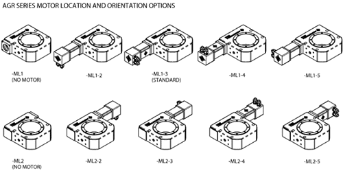
Motor Location (Required)
| Option | Description |
|---|---|
| -ML1 | Motor located on right side of stage housing, standard (see diagram) |
| -ML2 | Motor located on left side of stage housing (see diagram) |
Motor Orientation (Optional)
| Option | Description |
|---|---|
| -2 | Motor orientation 2 (see diagram) |
| -3 | Motor orientation 3, standard (see diagram) |
| -4 | Motor orientation 4 (see diagram) |
| -5 | Motor orientation 5 (see diagram) |
Travel (Required)
| Option | Description |
|---|---|
| Continuous travel (standard) | |
| -TR015 | Limited travel, ±7.5 degrees |
| -TR030 | Limited travel, ±15 degrees |
| -TR045 | Limited travel, ±22.5 degrees |
| -TR060 | Limited travel, ±30 degrees |
| -TR075 | Limited travel, ±37.5 degrees |
| -TR090 | Limited travel, ±45 degrees |
| -TR105 | Limited travel, ±52.5 degrees |
| -TR120 | Limited travel, ±60 degrees |
| -TR135 | Limited travel, ±67.5 degrees |
| -TR150 | Limited travel, ±75 degrees |
| -TR165 | Limited travel, ±82.5 degrees |
| -TR180 | Limited travel, ±90 degrees |
| -TR195 | Limited travel, ±97.5 degrees |
| -TR210 | Limited travel, ±105 degrees |
| -TR225 | Limited travel, ±112.5 degrees |
| -TR240 | Limited travel, ±120 degrees |
| -TR255 | Limited travel, ±127.5 degrees |
| -TR270 | Limited travel, ±135 degrees |
Note: -TRxxx limited travel options contain an extra 2 degrees of overtravel between the nominal travel and the electrical limit on each side (Ex: -TR270 contains ±135 degrees of nominal travel, with ±137 degrees of travel between electrical limits).
Limits (Required)
| Option | Description |
|---|---|
| -LI1 | Normally-closed, end-of-travel limit switches with 9-pin connector |
| -LI2 | Normally-open, end-of-travel limit switches with 9-pin connector |
Direct Rotary Feedback (Optional)
| Option | Description |
|---|---|
| -E1 | Direct, amplified-sine output encoder |
| -E2 | Direct, square-wave TTL output encoder, X5 multiplication |
| -E3 | Direct, square-wave TTL output encoder, X50 multiplication |
Tabletop (Optional)
| Option | Description |
|---|---|
| -TT1 | Metric tabletop |
| -TT2 | English tabletop |
Mounting Plate (Optional)
| Option | Description |
|---|---|
| -MP1 | Universal English/metric mounting plate |
Seals (Optional)
| Option | Description |
|---|---|
| -SL1 | Labyrinth seal |
Metrology (Required)
| Option | Description |
|---|---|
| -PL0 | No metrology performance plots |
| -PL1 | Metrology, uncalibrated with performance plots |
| -PL2 | Metrology, calibrated (HALAR) with performance plots |
Integration (Required)
Aerotech offers both standard and custom integration services to help you get your system fully operational as quickly as possible. The following standard integration options are available for this system. Please consult Aerotech if you are unsure what level of integration is required, or if you desire custom integration support with your system.
| Option | Description |
|---|---|
| -TAS | Integration - Test as system Testing, integration, and documentation of a group of components as a complete system that will be used together (ex: drive, controller, and stage). This includes parameter file generation, system tuning, and documentation of the system configuration. |
| -TAC | Integration - Test as components Testing and integration of individual items as discrete components that ship together. This is typically used for spare parts, replacement parts, or items that will not be used together. These components may or may not be part of a larger system. |