Specifications
ATX115SL/SLE Specifications
| Mechanical Specifications | ATX115SL/ATX115SLE | |||||
|---|---|---|---|---|---|---|
| Travel | 50 mm | 100 mm | 150 mm | |||
| Accuracy(1) | SL | Uncalibrated | ±6 µm | ±6 µm | ±7 µm | |
| Calibrated(2) | ±0.75 µm | ±1 µm | ±1 µm | |||
| SLE | Uncalibrated | ±2 µm | ±3 µm | ±4 µm | ||
| Calibrated(2) | ±0.5 µm | ±0.6 µm | ±0.6 µm | |||
| Resolution (Minimum Incremental Motion) | SL | 0.05 µm(3) | ||||
| SLE | 0.025 µm (-E1 feedback option)(6) 0.1 µm (-E2 feedback option) 0.2 µm (-E3 feedback option) | |||||
| Bidirectional Repeatability(1) | SL | ±0.5 µm | ||||
| SLE | ±0.15 µm | ±0.2 µm | ±0.2 µm | |||
| Horizontal Straightness(1) | ±1.25 µm | ±1.5 µm | ±1.75 µm | |||
| Vertical Straightness(1) | ±1.25 µm | ±1.5 µm | ±1.75 µm | |||
| Pitch | 60 µrad (12 arc-sec) | 70 µrad (14 arc-sec) | 80 µrad (16 arc-sec) | |||
| Yaw | 40 µrad (8 arc-sec) | 50 µrad (10 arc-sec) | 60 µrad (12 arc-sec) | |||
| Maximum Speed(5) | 2.0 mm/rev Ball Screw | DC Motor (-M1, -M2) | 100 mm/s | 100 mm/s | 100 mm/s | |
| DC Motor (-M3, -M4) | 220 mm/s | 220 mm/s | 180 mm/s | |||
| Stepper Motor (-M5) | 60 mm/s | 60 mm/s | 60 mm/s | |||
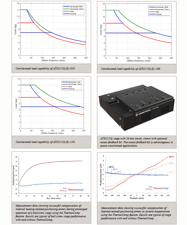
| Load Capacity | Horizontal | 14 kg | ||||
| Side | 10 kg | |||||
| Vertical (Axial) | 7 kg | |||||
| Moving Mass | 0.8 kg | 1.0 kg | 1.3 kg | |||
| Stage Mass | 3.2 kg | 3.8 kg | 4.5 kg | |||
| Material | Anodized aluminum | |||||
Certified with each stage.
Available with Aerotech controllers.
Achieved with Aerotech rotary motor with amplified sine encoder. Specification is unidirectional.
Achieved with Aerotech rotary motor with 10,000 lines/rev digital encoder. Specification is unidirectional.
Requires the selection of an appropriate amplifier with sufficient voltage and current.
Requires motor with 1 Vpp amplified sine encoder (-M3, -M4 motor options) and linear amplifier.
Specifications listed are valid for non-foldback kit options. Contact factory for specifications when a foldback kit option (-FBx) is ordered.
| Electrical Specifications | ATX115SL/ATX115SLE |
|---|---|
| Drive System | Brushless Rotary Servomotor (-M1 through -M4) Stepper Motor (-M5) |
| Feedback (Linear Encoder - SLE Version Only) | Incremental: 1 Vpp (-E1 feedback option) or 0.05 μm TTL (-E2 feedback option) Absolute: EnDat 2.2 (-E3 feedback option) |
| Feedback (Rotary Encoder) | Incremental: 10,000-Line TTL (-M1, -M2 motor options) |
| Maximum Bus Voltage | 48 VDC |
| Limit Switches | 5 V, Normally Closed |
ATX115SL Charts 

Dimensions
ATX115SL/SLE  Enlarge Image
Ordering Information
ATX115SL/SLE Series Mechanical-Bearing, Screw-Driven Linear Stage
Direct Linear Feedback (Required)
| Option | Description |
|---|---|
| SL | No direct linear feedback |
| SLE-E1 | Incremental linear encoder, 1 Vpp |
| SLE-E2 | Incremental linear encoder, 0.05 µm digital TTL output |
| SLE-E3 | Absolute linear encoder |
Travel (Required)
| Option | Description |
|---|---|
| -050 | 50 mm travel |
| -100 | 100 mm travel |
| -150 | 150 mm travel |
Motor (Required)
| Option | Description |
|---|---|
| -M1 | DC servomotor with 10,000-line TTL encoder |
| -M2 | DC servomotor with 10,000-line TTL encoder and brake |
| -M3 | DC servomotor with 1000-line 1 Vpp encoder |
| -M4 | DC servomotor with 1000-line 1 Vpp encoder and brake |
| -M5 | Stepper motor |
Foldback Kit (Optional)
| Option | Description |
|---|---|
| -FB1 | Foldback kit for ATX115 motor |
ThermoComp (Optional)
| Option | Description |
|---|---|
| -TCMP | ThermoComp integrated thermal compensation |
Metrology (Required)
| Option | Description |
|---|---|
| -PL1 | Metrology, uncalibrated with performance plots |
| -PL2 | Metrology, calibrated (HALAR) with performance plots |
Integration (Required)
Aerotech offers both standard and custom integration services to help you get your system fully operational as quickly as possible. The following standard integration options are available for this system. Please consult Aerotech if you are unsure what level of integration is required, or if you desire custom integration support with your system.
| Option | Description |
|---|---|
| -TAS | Integration - Test as system Testing, integration, and documentation of a group of components as a complete system that will be used together (ex: drive, controller, and stage). This includes parameter file generation, system tuning, and documentation of the system configuration. |
| -TAC | Integration - Test as components Testing and integration of individual items as discrete components that ship together. This is typically used for spare parts, replacement parts, or items that will not be used together. These components may or may not be part of a larger system. |
Note: HDZ bracket requires tabletop when mounting to a PRO stage.