Micro-vibration isolation first became necessary in laser research laboratories. Newport Research Corporation, beginning in 1969, satisfied this need with a series of isolation legs to support optical tables in laboratory applications. These isolators were designed to provide the best transmissibility, or ratio of isolated body motion to floor motion, over the widest possible bandwidth.
Pneumatic isolators consist primarily of an air chamber that is sealed with a flexible diaphragm. This air chamber supports the payload on a cushion of air. Self-leveling designs incorporate leveling valves to control air into and out of the air chamber. The purpose of the leveling valve is to make the isolator performance relatively independent of load and to return the platform to the proper position after changes in load distribution.
The isolator becomes part of a payload mass/spring/damper system. Essentially, pneumatic isolators act as a mechanical filter. Before they begin isolating, floor motion is amplified at their natural frequency. The natural frequency is given as:

where “k” is the system stiffness and “m” its mass.
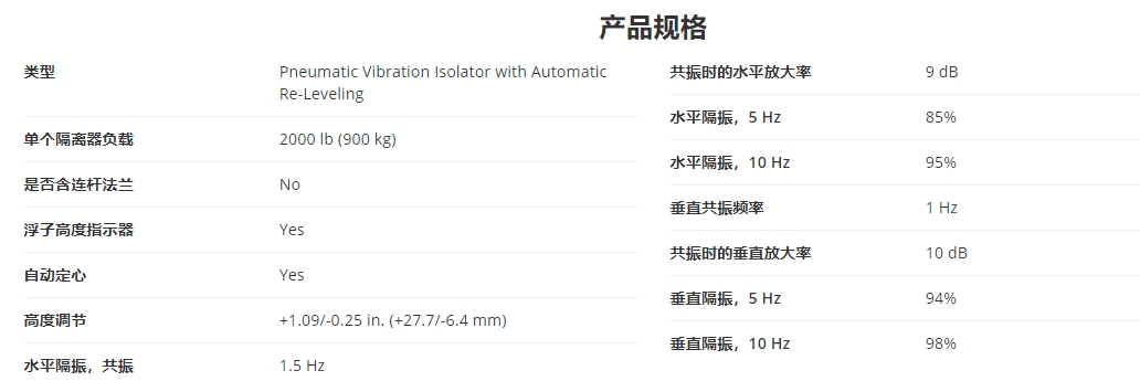
Thus, the requirement for best isolation and maximum bandwidth implies that the natural frequency be as low as possible; normally 1–2 Hz. At floor vibration frequencies below the isolated system natural frequency, the isolator transmissibility is one and the payload motion is the same as the floor motion. At the system's natural frequency, the passive isolator amplifies floor motion by a factor of about 3–10, depending on damping. Heavily damped systems amplify less than lightly damped systems. At 1.41 times the natural frequency, transmissibility is again one. Isolation begins above the 1.41 x fn frequency point. As the vibration frequency increases, the transmissibility rolls off with a slope of -40 dB/decade. This means the isolation improves by a factor of 100 for every factor of 10 increase in frequency.
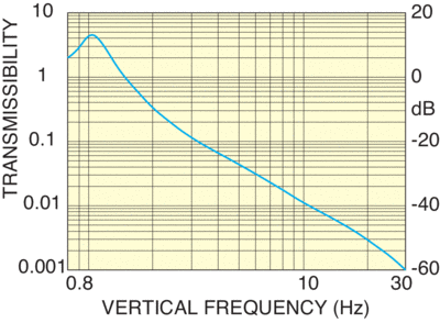
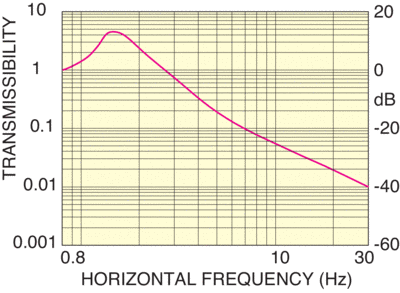
For example, given a system with a 2 Hz natural frequency; and thus a transmissibility of one at 2.8 Hz (1.41 x 2); the transmissibility at 28 Hz would be –40 dB, or 0.01. Horizontal isolation in a Newport isolator is achieved by use of a pendulum system. The behavior of the pendulum horizontal isolator is basically the same as that of the vertical pneumatic isolator. In this case, the pendulum natural frequency is given by:

where “L” is the pendulum length and “g” is the acceleration due to gravity. The horizontal natural frequency is generally about 1.5 Hz. The passive vibration isolator then provides vibration attenuation starting at about 2–3 Hz and improving as the vibration frequency increases. The measure of quality in passive isolation systems for research applications was low natural frequency for better isolation — the lower the better. The downside of passive mass/spring/damper isolators is that they are a very soft suspension system. Further, the better the isolation, the softer they are. The slightest disturbance of the payload can result in significant payload motion and settling times of up to ten seconds. This is generally acceptable in the research world. However, as the research projects filtered down into the manufacturing and inspection environment, long settling times in automated systems became unacceptable due to cycle time cost. Further, many precision manufacturing and measurement operations cannot tolerate base motion or tilt. The measure of quality for a manufacturing isolation system has taken on a broader meaning that is application dependent. No longer is “lowest natural frequency” the only criteria by which passive isolation systems are judged.
Performance criteria for evaluating pneumatic isolators include the following:
Isolation (low natural frequency)
Settling time (vertical and horizontal after an agreed upon disturbance)
Leveling accuracy
Ability to remain level during load changes such as stage movement
Amount of horizontal motion acceptable as a result of stage reaction forces
The isolator's overall performance is a compromise between each of the criteria.
For a given load, the isolation performance is primarily a function of the isolator compliance volume. Reduced diaphragm and leveling valve stiffness also improves isolation. All pneumatic isolators must also incorporate some vertical pneumatic damping or the isolator would be unstable. Thus, conventional isolators consist of a spring (compliance) chamber that is connected to a damping chamber. The primary design compromise is between isolation and damping. Improved damping results in a sacrifice of isolation — as damping is increased so is the natural frequency and thus the isolation bandwidth is decreased. Conventional isolators with these properties are available from a number of manufacturers.
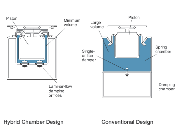
All Newport isolators designed since about 1991 have incorporated the patented Stabilizer™ approach. The Stabilizer “hybrid” chamber concept uses the compliance of the total isolator volume (both “chambers”). The unique Newport design incorporates a laminar flow damping element in a barrier that fits closely about the isolator piston within the overall isolator air volume. This approach allows a wide range of damping, from light for research applications to very heavy for industrial moving stage applications. Minimal natural frequency increase (isolation efficiency reduction) is seen in the heavily damped versions. Other manufacturers offer only the conventional two-chamber design with a small orifice connecting the chambers. The chamber adjacent to the diaphragm provides the compliance, or spring, of the isolator. The orifice and second chamber provide the system damping as air is forced through the orifice between the chambers. The orifice size is very critical. If it is optimized for floor vibration isolation, it will be too small to optimally damp large motion resulting from load changes or stage travel. In the conventional two chamber design used by other manufacturers, it is impossible to greatly increase vertical damping for seismic-level floor disturbances without raising the isolator natural frequency, impacting high frequency isolation, and decreasing damping for large disturbances.
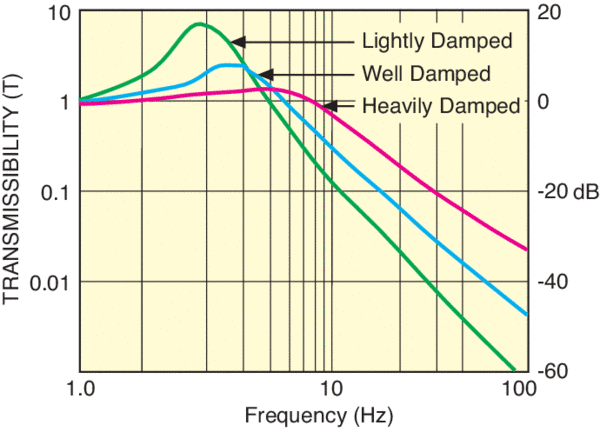
Damping is generally set to give transmissibility amplification of about 3 (9.5 dB) at the isolator/payload vertical resonance. This damping provides a good balance of low amplification at resonance and good isolation at higher frequencies. However, this is not enough damping for rapid settling after a stage move or other payload disturbance. There are two types of payload disturbance — those that do not change the isolator loading and those that do:
Disturbances that do not change the isolator loading include bumping the isolated payload by accident and touching the system to make adjustments. To improve settling time in these applications, part of the Newport laminar flow elements can be blocked (or specially designed in custom isolators) to limit amplification at resonance to about 2. This higher damping enables settling times of better than 3 seconds after a significant payload disturbance.
Disturbances that do change the isolator loading include loading or unloading parts in work or moving stage applications. In these applications, higher isolator damping enables the use of higher leveling valve gain (the ratio of valve air flow to payload height error). It is then possible to let in air to or exhaust air from the isolators more quickly without the system oscillating. Faster airflow makes it possible for the payload to remain more level during stage moves or parts loading and unloading.

Building on the high isolation Stabilizer technology, Damping was developed in 1997 to offer improved damping for moving payload applications. Damping isolation systems use constricted laminar flow orifice and high gain valve systems. Standard Damping configurations constrict the laminar flow by 50% and greatly improve system stability on moving loads. Custom designs can be further tuned to machinery needs by adjusting laminar flow, valve gain and even the diaphragm stiffness.
